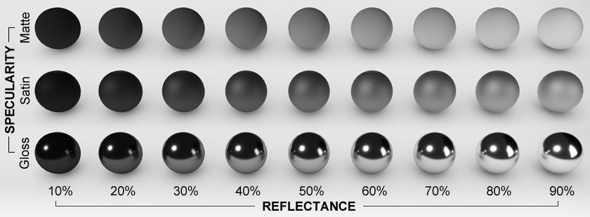
The reflectance of a particular object or instance of material refers to the ratio of the total amount of light or electromagnetic radiation that is reflected from it’s surface compared to the total amount originally incident upon it. Reflectance is also sometimes referred to as a material’s reflection coefficient or reflection factor. As shown in Figure 1, a material’s reflectance is directly related to how bright we perceive that material to be.

Figure 1: A set of spheres showing the visual effect of different levels of reflectance and specularity.
It is important to note that reflections only occur when light or radiation hits the boundary between two media in which light travels at different speeds, as measured by their refractive index. If two media have the same refractive index, light and radiation will be unaffected by the boundary between the two so there will be no reflection or refraction. If they are different, the amount of reflection is governed by the properties of both materials, so the reflectance of a material adjacent to air will be very different to the reflectance of that same material adjacent to water or even argon gas.
Thus, unless otherwise specified, when referring to building materials and in fact most physical materials, any given reflectance value implicitly assumes the boundary between that material and air.
Colour and Reflectance
An object is only visible because the eye receives some of the light that is reflected off it. If an object reflected no light, it would appear to us as a featureless black silhouette. The definition of black is the complete absence of all colours within the light spectrum. On the other hand, the definition of white is the equal presence of all colours within the light spectrum. Materials with a colour that is not black or white must therefore lie somewhere between these two bounding extremes.
The upshot is that colour and reflectance are directly related in all opaque and most translucent materials. White materials have the highest reflectances as they reflect all parts of the visible colour spectrum roughly equally. Coloured materials will always have lower reflectances as some parts of the colour spectrum must be reflected less than others in order for their colour to be descernable. It follows that the darker the colour appears, the lower its reflectance. This continues right down to the darkest of all colours - black. Black objects will always have the lowest reflectances as, by definition, they do not reflect any parts of the visible colour spectrum.
For more details on the effects of surface colour, see the Colour topic.
Reflection Direction
When people think of a reflection, they usually think only of specular reflection. However, the reflectance property is not concerned in any way with the direction of the reflected energy, only the total overall amount. This is because the angular distribution of reflected light or radiation is a function of surface treatment. The same material with a particular colour could be made almost matte with a very rough finish or specular with a highly polished finish, but the overall reflectance of both surfaces would still be the same.
It is important to note that matte white materials can often have a higher overall reflectance than shiny or glossy materials, including a typical glass mirror. For more information, see the Specularity topic.
Visual Estimation
Another important note is that it is actually very difficult for us to determine or even compare the levels of reflectance and specularity of different materials and colours just by looking at them.
For example, polished black cars always look the shiniest as you can clearly see the reflection of lights and other objects off their surfaces. However, a similarly polished white car will typically have a higher specular component, it is just that the diffuse component is so much greater as well that it masks the clarity of the specularly reflected images. Thus, to us, it doesn’t look as shiny as the black car unless viewed from very close to grazing incidence.
At close to grazing incidence (where the view angle is close to 90° to the surface normal), diffuse reflections are significantly less due to Lambert's cosine law, so the specular component from the white car becomes less masked and therefore more clearly defined.
Reflectance or Reflectivity
Reflectance can be a complex phenomenon affected by molecules and sub-atomic particles both at and below the surface of a material. For most reasonably thick opaque materials, reflection occurs within the first few nanonmetres of the surface and any light transmitted more than about 100nm into the material is quickly absorbed. In such simple cases, their overall reflectance value is essentially the same as their reflectivity.
However, for transparent, translucent or extremely thin materials there are additional effects such as internal reflections from the rear face or scattering from non-homogenous particulates that can result in highly divergent values for overall reflectance and reflectivity. In these cases, reflectivity can be thought of as the lower limit of reflectance, or the reflectance resulting only from the initial intersection of the light with the surface. Any other internal effects serve only to increase the overall reflectance whilst the reflectivity remains the same.
This is a very important distinction that is discussed in more detail within the Reflectivity and Reflectance topic.
Calculating Reflectance
It is possible to calculate the reflectivity and initial reflectance for the boundary between any two transparent media using Fresnel equations if the refractive index of both media are known.
The first step is to find the angle of refraction for the light or radiation transmitted into the second material using Snell's law. You can find refractive index values for a wide range of materials, liquids and gasses at the bottom of the Refractive Index topic.
This can be simply re-arranged to give the angle of refraction:
where:
- n1 is the refractive index of the medium the light is travelling from,
- n2 is the refractive index of the medium the light is travelling into,
- θi is the angle of incidence, in degrees or radians, and
- θx is the angle of refraction, in degrees or radians.
The specification of degrees or radians means that it depends upon which maths library you are using and how it requires you to provide angle input for the sin and cos trigonometric functions. If you are using a pocket calculator, you can usually switch modes and enter either degrees or radians. If you are implementing these equations in computer code, you will very likely need to use radians.
Polarization
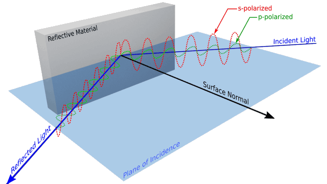
The reflective behaviour of light also depends upon the orientation of the incident light’s polarization as it strikes the surface. The Fresnel equations therefore have two variants for both s- and p-polarized light. Figure 2 illustrates the difference between these two types of polarization.

Figure 2: Illustrating the difference between s-polarized and p-polarized light incident on a surface.
For s-polarized light, where the wave is at 90° to the plane of incidence, the reflectivity is given by:
where:
- Rs is the reflectivity and initial reflectance for s-polarized light,
For p-polarized light, where the wave is parallel to the plane of incidence, the reflectivity is given by:
where:
- Rp is the reflectivity and initial reflectance for p-polarized light.
For unpolarized light with an equal mixture of s- and p- components, the results of the two equations must be averaged:
These equations calculate the hemispherical reflectance that occurs when the light or radiation first hits the boundary at the given incidence angle. They do not specify anything about the angular distribution of the reflected energy or what portion of the reflected energy is specular.
Hemispherical Reflectance
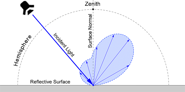
When referring to building materials, the term reflectance is usually taken to mean hemispherical reflectance. This is the relative fraction of radiation that bounces back somewhere into the hemisphere whose zenith is normal to the surface plane and on the same side of the surface as the incident radiation source, as shown in Figure 3. Any radiation that travels deeper into the opposite hemisphere on the other side of the surface does so only via transmission.
Transmittance and Absorptance
Light reflectance is directly related to light transmittance such that:
where:
- R is the reflectance of the surface,
- T is the transmittance of the material, and
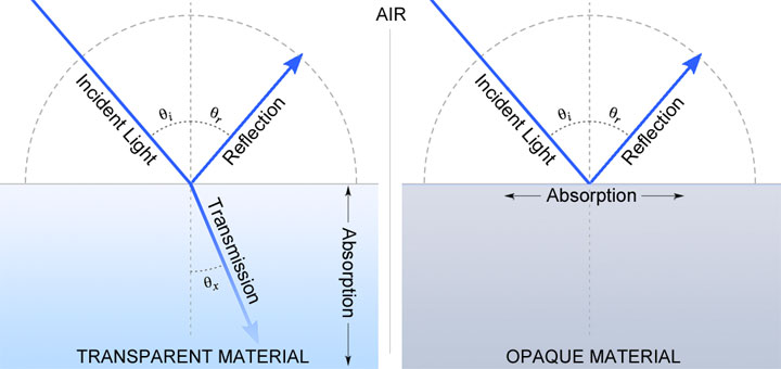
The transmittance value refers to the amount of light or radiation that passes into the material. The effect of light absorptance is then to reduce the value of the transmitted component as it travels further through the material.

Figure 2: The relationship between reflection, transmission and absorption in transparent and opaque materials.
In a reasonably thick opaque material, the absorptance is such that all of the light is very quickly absorbed before it has travelled very far. For transparent materials, the effect of absorption is seen when light passes out of the rear face. At that point, some will have been absorbed and some will have been reflected back towards the front face due to internal reflectance.
Units and Measures
As described earlier, reflectance refers to the ratio of the total amount of light or electromagnetic radiation reflected from a surface compared to the total amount originally incident upon it. Thus it is a dimensionless factor with a value between 0 and 1.
Simple Calculation
Based on the trichromatic nature of human visual perception, it is possible to get a reasonable estimate of reflectance if you know the individual RGB color component values. The simplified equation for this is as follows, with the multipliers for each colour component derived from our overall sensitivity to wavelengths in each of the red, green and blue bands.
where:
- R is the reflectance value of the color (0-1),
- Red is the Red component of the color (0-1),
- Green is the Green component of the color (0-1), and
- Blue is the Blue component of the color (0-1).
Light Reflectance Value
Light reflectance value (LRV) is another measure similar to reflectance commonly used by paint manufacturers and interior designers. It is defined in BS 8300:2009+A1:2010 as the total quantity of visible and useable light reflected by a surface in all directions and at all wavelengths when illuminated by a light source. Instead of a factor, LRV is given on a scale from 0% to 100%. Zero represents the ideal absolute black and 100% the ideal perfectly reflective white. Real physical materials range from about 5% for the blackest of matte blacks up to 85% for the brightest white, though some fluorescent yellow materials can measure up to 90-92%.
Reflectance and LRV can be measured using a gonioreflectometer or an integrating sphere.
A Gonioreflectometer

Figure 4: An example of a Gamma Scientific Model 191 Series Reflectometer Head on a rotary system for testing multiple samples..
A Gonioreflectometer is a device in which a highly directional light source and light detector can be rotated independently around a sample material. For each position of the light source, the light detector can be rotated 180° around the reflector in order to measure the angular distribution of reflectance. A full 3D angular distribution can be achieved by incrementally moving the detector around the full 180°, incrementally tilting the sample and then repeating the 180° detector movement.
As you can imagine. accurately measuring the angular distribution for each incidence angle can be very time consuming and generates a lot of data. However, this data is very useful, expoecially in the field of computer graphics and rendering as it allows for the generation of realistic bidirectional reflectance distribution functions (BRDF).
An Integrating Sphere

Figure 5: An example of a LabSphere RT-060-SF integrating sphere.
Integrating spheres can be used to measure both reflectance and transmittance, though not at the same time as they have to be configured slightly differently. The basic idea is that the inside of a sphere is coated with a highly diffuse reflective material with very low losses due to transmission or surface absorption, typically Barium Sulfate or PTFE.
The idea is that, with diffuse reflections and the fact that all the surface normals of a sphere point directly at its center, the light reaching any point on the surface of the sphere will be reflected to all other points so, regardless of the initial direction of light, its energy will be spread evenly over all parts of the sphere. Thus a detector with a known aperture size can be used to determine the overall total amount of energy within the sphere by simply multiplying the energy it receives by the reciprocal of the ratio between its area and the total area of the sphere.
The advantage of an integrating sphere over a gonioreflectometer is that total reflectance can be calculating with just a single measurement. However, an integrating sphere cannot be used to determine the angular distribution of reflected energy.
Example Values
| COLOR | LRV |
|---|---|
| White | 70 - 90% |
| Ivory and Cream | 55 - 71% |
| Light Yellow | 65 - 70% |
| Light Buff | 40 - 56% |
| Light Green | 40 - 50% |
| Medium Green | 15 - 30% |
| Orange | 15 - 30% |
| Medium Blue | 15 - 20% |
| Dark Blue | 5 - 10% |
| Medium gray | 15 - 30% |
| Red and Maroon | 5 - 18% |
| Medium and Dark Brown | 3 - 18% |
| Black | 1 - 4% |
Table 1: Some example Light Reflectance Values for common colours.
References
Click here to comment on this page.

